Training on atmospheric dispersion in urban environments
4. Impact of buildings on flow and dispersion
Buildings and other structures disturb the flow of air. The urban airflow is highly complex, governed by the buildings and the speed and direction of the approaching flow. To describe how buildings impact flow in cities, an idealized flow around one or two simple buildings is first considered. In the real city the airflow patterns are more complex due to the presence of many buildings with different shapes and streets in different configurations.
Idealized flow around a single building is shown schematically in figure 4.1. There are three main flow zones:
- The displacement zone where the approaching air is deflected around and over the building,
- The relatively isolated cavity zone on the leeward side of the building, and
- Downwind from the building, a highly disturbed area called the wake zone.
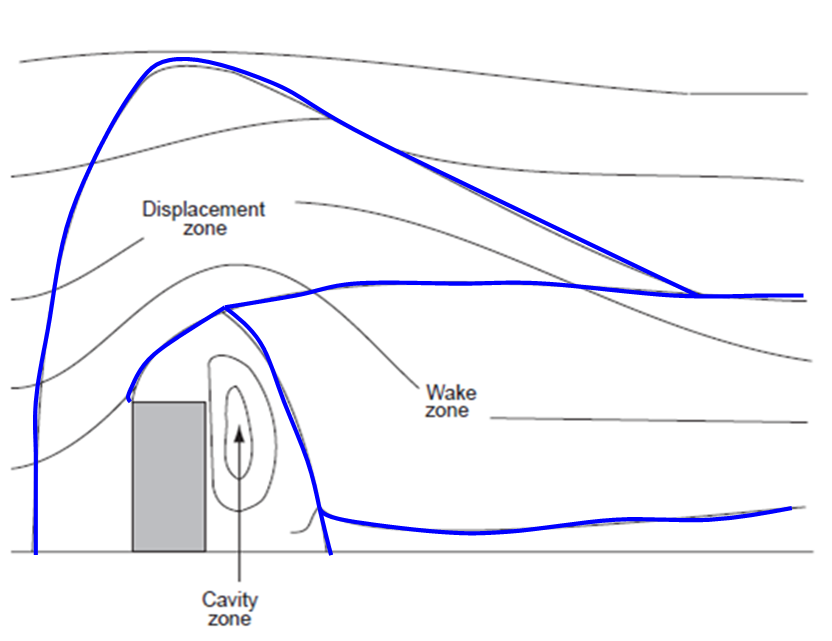
Figure 4.1: Air flow around a single building with the three main flow zones: displacement zone, cavity zone and wake zone. [1]
The prevailing dispersion pattern depends upon both the release height and the receptor location. Figure 4.2 shows a plume in the case of a release in the displacement zone of flow where the dispersion can be considered undisturbed by the building.
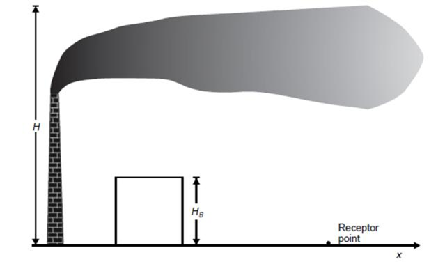
Figure 4.2: Air flow in the displacement zone. [1]
Figure 4.3 shows a plume in the case of release in the wake zone, a region of downward mixing. This effect, known as building downwash, pulls the plume down to ground level and leads to elevated concentrations immediately downwind of the source.
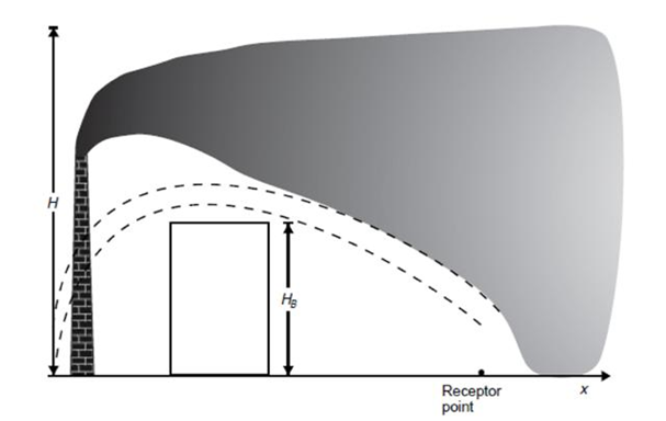
Figure 4.3: Air flow in the wake zone. [1]
Figure 4.4 shows a plume in the case of release in the cavity zone, a region where the flow is highly turbulent and generally recirculating. The agent released is entrained and can be trapped in the immediate vicinity. There is an increase of vertical dispersion, enhancing the initial growth of the plume and the concentrations at ground-level.
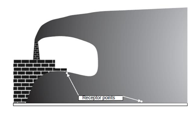
Figure 4.4: Air flow in the cavity zone. [1]
To understand the impact of buildings on flow, simple flows in idealized
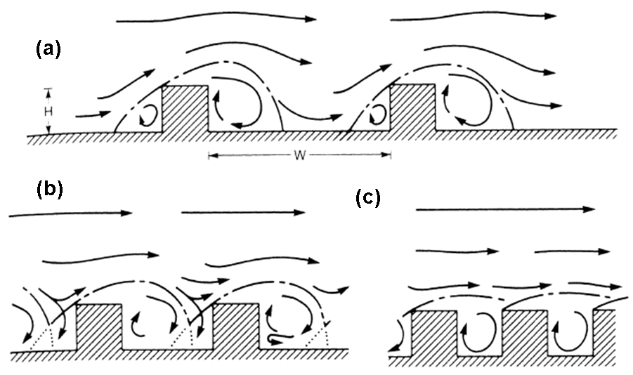
Figure 4.5: 2D Flow regimes as function of width-to-height ratio [from Oke 1987]:
The nature of the flow is mainly determined by the ratio of the width between buildings (w) to the building height (h). For the case of long buildings, which can be considered as two-dimensional case, three flow regimes have been identified: isolated roughness regime, wake interference regime and skimming regime. More details on those regimes.
When the flow is three-dimensional, the effects of vertical side edges of the buildings are important.
Figure 4.6 depicts an idealized airflow around an isolated building; showing recirculation vortices from the
top and the lateral
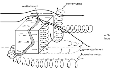
Figure 4.6: 3D airflow patterns in case of an isolated building, from Hosker 1984 [5].
Figure 4.7: 3D flow in urban-canyon, from Britter and Hunt 1979 [6].
The following section describes atmospheric dispersion models in general.
<< Previous | >> Next